Digital
Automatic Gain Control for Radio Transceivers
© 2003, Douglas T. Smith Editorial Services
Digital gain-control algorithms in a
modern transceiver.
(Updated 5-26-2003)
Today's radio receivers need to handle a
tremendous range of signal amplitudes, especially
on HF. From a noise floor of about 0.1 uV to a
maximum usable signal of around 1 V, the range is
140 dB! Users would like receiver output signals
to remain constant in amplitude over most of that
range. Automatic gain control or AGC does the job
by setting receiver gain to be inversely
proportional to input level.
Similarly, transmitters must employ gain
control to prevent overdrive of their final power
amplifiers. Transmitter gain control is usually
called automatic level control or ALC.
Here, I discuss AGC and ALC as implemented in
the Ten-Tec Orion. Digital signal processing (DSP)
and its interaction with analog electronics are
emphasized. The first section covers a refinement
of the digital AGC I described in recent editions
of The ARRL Handbook and in my DSP book.1,2
IF-DSP and Digital AGC
IF-DSP receivers produced at the time of this
writing generally employ both analog and digital
AGC systems. That is because the DSP section
alone cannot achieve the 140 dB of dynamic range
required. Analog AGC kicks in at some high input
level to prevent overload of the analog-to-digital
converter, thereby extending dynamic range.
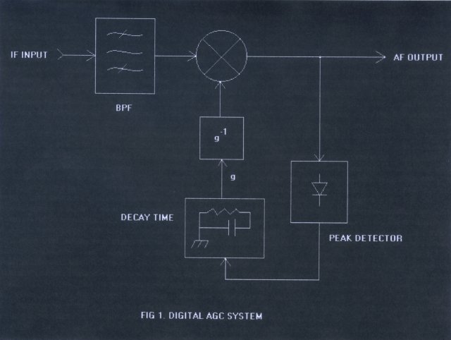
At input levels below actuation of analog
AGC, digital AGC is solely responsible for
leveling output signals. DSP peak-detects IF
signals falling within the desired passband and
adjusts a digital gain-control factor to maintain
constant peak output. Fig 1 is a simplified block
diagram of this system, which is identical to
that of a traditional analog AGC.
In digital AGC systems, it is relatively easy
to provide a variable threshold or "knee."
Input signals below the threshold do not actuate
the digital AGC and are not compressed. At
thresholds well above the receiver noise floor, a
receiver therefore gets quiet when only puny
input signals are present in the passband. At
thresholds near the noise floor, all signals are
boosted to meet the output-level criterion. The
net effect of a variable threshold is very much
like that of an IF gain control.
For settings FAST, MED and SLOW, the Orion's
threshold is set to about 3 uV. That means you
have about 30 dB of linear range between the
noise floor and the point at which AGC starts
operating. In PROG, you can set the AGC threshold
manually. A low threshold (0.35 uV) means all
signals are boosted to a constant peak output
level; a high threshold (191 uV) means signals
must reach about 12 dB over S-9 before
compression occurs.
AGC decay rates describe how quickly IF gain
increases in the absence of signals over the
threshold. In the Orion, IF gain increases
geometrically with time-- that is, by a
programmable number of dB per second. The SLOW
setting runs about 5 dB/s, while the FAST setting
is many hundreds of dB/s. The OFF setting makes
decay time very short. FAST and OFF are such that
the AGC may actually destroy the envelopes of
signals in the passband. The net result is
clipping, which produces distortion-- but you
wanted it fast, right?
It is also fairly easy to implement a peak-hold
or "hang" function that retains the
most-recent peak for an adjustable period of time.
The S meter reflects the behavior of the AGC
system in all ways. Attack time is generally
fixed.
When noise reduction is engaged, it is desirable
to artificially reduce the AGC threshold;
otherwise, things get very quiet indeed! Because
of that, you may notice that your audio level
increases as you turn on noise reduction; but
signal-to-noise ratio improves and that is the
criterion, after all.
Analog and Digital AGCs Together
IF-DSP receivers use digital filtering for
their final selectivity. That means the DSP
samples more IF bandwidth than what is desired at
the receiver output. Very large input signals may
actuate analog AGC, reducing the gain between
antenna and DSP. For in-band signals, that is no
problem; but if the large signals are outside the
final passband, analog gain is also reduced for
in-band signals. The receiver's output amplitude
will bop up and down as the analog AGC is pumped
by the interference.
The general solution is to employ digital
gain compensation. To do it, the DSP must have
information about the amount of analog gain
reduction and the ratio of in-band signals to
interference.
Digital Gain Compensation
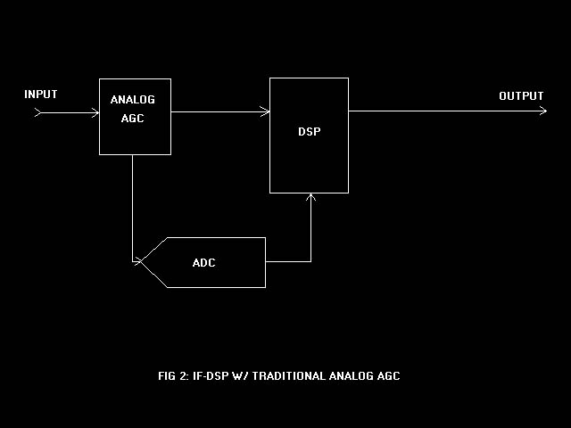
For traditional analog AGC systems not under
the control of the DSP, analog gain-reduction
information may be obtained by digitizing the AGC
voltage. See Fig 2. The voltage value is used to
look up a gain-reduction factor from a table
stored in non-volatile memory. Such a table may
be built using measurements of the actual
hardware. Minor unit-to-unit variations are
readily handled by placing the digital gain-compensation
point inside the main digital AGC loop, as
described below.
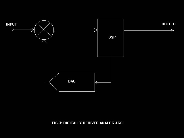
An alternate approach involves generating the
analog AGC voltage in the DSP itself. See Fig 3.
A digital-to-analog converter develops a voltage
for application to analog gain-controlled stages.
The chief drawback to the scheme is a significant
delay between peak detection and gain change,
since signals must propagate all the way through
the DSP section before being detected. That can
be compensated with a delay in the analog IF
strip; but typically, the required delays of
several ms are impractical.
In any case, call the analog gain-reduction
factor g, where 0<g<1. For
example, were g=1/2, analog gain reduction
would be -20log(1/2) or about 6 dB. Now it
remains for the DSP to compute how much of that
gain reduction was caused by in-band signals and
how much by interference. If all of it were
caused by in-band signals, no gain compensation
would be necessary and we would use digital gain-boost
factor f=1. If all of it were caused by
interference, in-band signals would have to be
boosted by a factor f=g-1=2.
For cases in between those two extremes, the
procedure is a little tricky because f
cannot be described by a single equation.
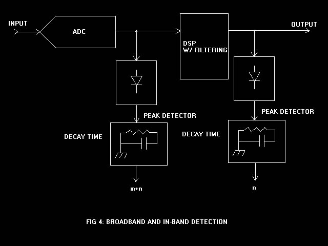
A Case Study in Gain
To get information about the ratio of in-band
signals to interference, the DSP peak-detects
both the broadband IF (everything that is
digitized) and the receiver output. See Fig 4.
Call the peak interference level m and the
peak in-band signal n. The peak of the
broadband IF is therefore the sum of the
interference and in-band signals, or m+n.
The DSP calculates the ratio:
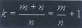
The next step is to determine whether n
by itself was large enough to actuate analog AGC.
The DSP does that by comparing k with g-1.
The algorithm accounts for three cases in the
comparison.
Case 1: If k<g -1,
then n by itself is large enough to
actuate analog AGC and the gain-boost factor used
is f=k. The ratio of signals solely
determines the boost factor.
Case 2: If k>g -1, then n
by itself is not large enough to actuate analog
AGC and the gain-boost factor is f=g
-1. Analog gain reduction solely determines
the boost factor.
Case 3: When k=g -1,
it obviously does not matter which is used as the
gain-boost factor since they are equal.
Remember that when analog AGC is inactive, no
gain boost need be applied.
Note that g depends only on the
characteristics of the analog gain-controlled
stage or stages; k depends on the ratio of
in-band and interfering signals, irrespective of
the analog section. The two possible gain-boost
variables therefore produce different functions
and curves. The curves are guaranteed to meet
where k=g -1.
Gain Boost Belongs Inside the AGC Loop
The decay time of the broadband m+n
peak detector must match that of analog AGC as
closely as possible. The decay time of the in-band
n peak detector may be altered at will to
get the desired response. Placing the digital
gain boost inside the AGC loop assures that a
constant peak output level will be maintained
even in the face of minor variations in analog
gain control. See Fig 5.
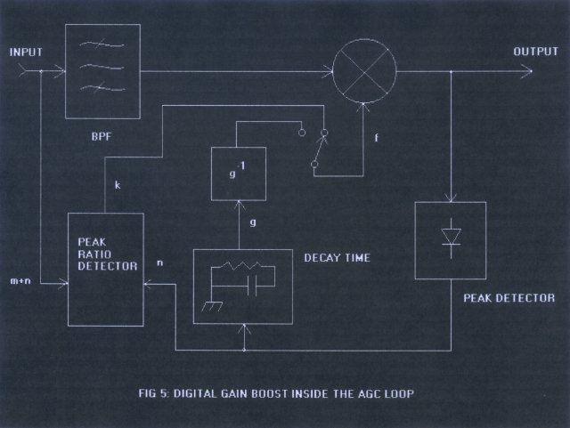
Inside the loop, we apply digital gain boost
to signals before they are peak-detected.
Therefore, the main digital AGC loop prevents
them from exceeding the set output level when
interference-- and k or g-1--
rapidly increase. In addition, IF gain may be
manually reduced by artificially increasing the
analog AGC voltage without deleterious effects.
Finally, gain-boost factor f may be
directly used to compensate a signal-strength
meter by the appropriate amount. Just as the
receiver output level remains constant in the
presence of interference, so does the S meter.
When IF gain is manually reduced, the S meter
goes down-- not up, as in so many rigs.
Preventing AGC Overshoot
A DSP normally stores signals to be processed
in a series of buffers. Signals from recent to
old are therefore available. That presents a neat
way of avoiding late adjustment of AGC or
overshoot.
When a big signal comes along, receiver input
amplitude may rise rapidly from the noise floor
to a value of some 100 dB greater, or more. A CW
signal with a fast rise time may necessitate a
gain-change rate of thousands of dB per second!
Digital AGC copes with that by detecting older
signals and applying the gain change to
more-recent signals before they are output. In
that way, the DSP "sees" the big signal
coming before it can destroy a constant
output level. The technique need not introduce
additional delays in baseband output because it
is only the detector that moves backward in time.
Digital ALC and Transmit Gain Control (TGC)
Transmitters are likely to have gains that
vary quite a bit with frequency, temperature and
supply voltage. Like receivers, they may be
called on to handle a large range of input levels
without exceeding a set output level. ALC serves
that purpose.
It is plausible to arrange for ALC in an IF-DSP
transmitter by digitizing an indication of
forward power, such as from a bridge, and
adjusting the drive signal applied to the exciter.
In that case, no analog gain-controlled stages
are needed; but it does reduce the available
dynamic range of the transmitter somewhat.
The other possibility is to employ a
traditional analog ALC with gain-controlled
stages. Still, some adjustment of drive from the
DSP is called for to maintain optimum performance
over wide ranges of frequency and output power.
TGC
TGC is a neat concept that was first
practiced at Collins Radio, as far as I know.3
It is a secondary ALC system that slowly changes
the maximum drive applied to a transmitter so
that the main ALC does not have to work so hard.
The benefits include a minimum of overshoot on
SSB and CW and prevention of ALC pumping. It
leads to an innovative system for AM transmitters
that achieves zero carrier shift, described below.
We must apply sufficient drive to achieve
desired output power; but we do not want to apply
more drive than absolutely necessary. When a DSP
can get information about the required level, it
can optimize drive. One reason to do so is to
maintain optimal RF rise and fall times and
shapes that minimize interference to others.
When an ALC-controlled transmitter is driven
hard, it rises rapidly to its set power level.
After it gets there, the ALC loop attempts to
reduce gain. If all that happens too fast, it
becomes very difficult to avoid spikes and other
artifacts in the output.
Digital TGC forces a DSP to examine ALC
voltage to determine the amount of gain reduction
occurring in analog. As in the receiver case, it
does that by digitizing the voltage and using it
as an address into a look-up table. When analog
gain reduction is excessive, the DSP is
programmed to reduce drive. In the absence of
ALC, it is programmed to increase drive to a
preset maximum. TGC usually changes quite slowly,
although it is often set to reduce drive quicker
than to increase it.
TGC is set to achieve a drive level slightly
higher than what is necessary to attain rated
power. A 3-dB margin is common. Note that no
matter what the set power level, TGC will alter
drive to match. That is handy in transmitters
that use ALC over a wide range of power levels.
A Unique AM ALC
Here is a novel AM ALC system that sports
zero carrier shift and 100% maximum modulation,
regardless of transmitter gain and baseband wave
shapes. Refer to Fig 6.
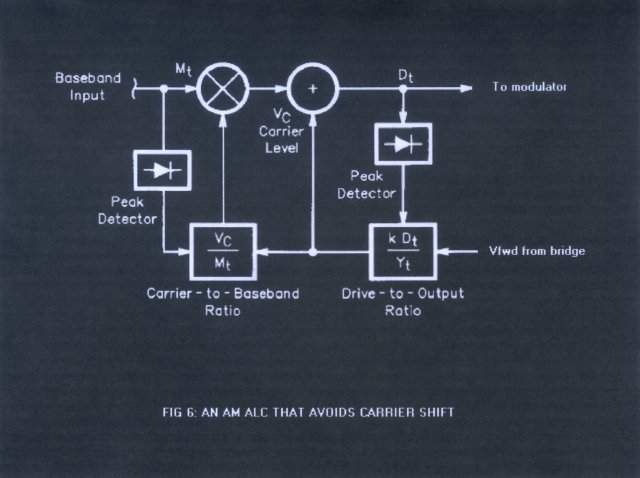
A DSP obtains information about peak
transmitter output power from a bridge, as above.
Since it already has information about its peak
drive level, it can compute the transmitter's
gain. It is then relatively easy to find the
drive level that produces a carrier of exactly 25%
of the set power level.
An audio compressor is employed that sets the
maximum baseband peak level identical to that of
the carrier. When modulation is performed, the
result is a 100%-modulated AM wave. The audio
compressor uses a full-wave rectifier. If the
baseband voltage had a higher negative peak than
positive, 100% downward modulation would be
reached in compression before 100% upward
modulation could occur.
Carrier amplitude does not change because the
transmitter gain calculation is performed on the
peak-detected combination of Vc+Mt,
where Vc is the peak
carrier level and Mt is
the peak modulation level. DSP computes the peak
drive level based on carrier plus modulation; it
computes the carrier level based on transmitter
gain. Carrier shift, therefore, is avoided
entirely-- Doug Smith, KF6DX.
For Further Reading
1. ARRL Handbook for Radio Communications,
2003, 80th edition, D. Reed, ed.;
ARRL, Newington, CT, 2002; ISBN: 0-87259-192-1.
2. Digital Signal Processing Technology,
D. Smith, ARRL, 2001, ISBN: 0-87259-819-5.
3. Single Sideband Systems and Circuits,
W. Sabin and E. Schoenike, eds; McGraw-Hill, New
York, 1995; ISBN: 0-07912-038-5.
|
| |
|
|
 Douglas
T. Smith Editorial Services
Douglas
T. Smith Editorial Services