and screen shot bitmaps

Figure 1. ORION front panel

Figure 2. ORION screen and surrounding control buttons

Figure 3. ORION front panel, left side
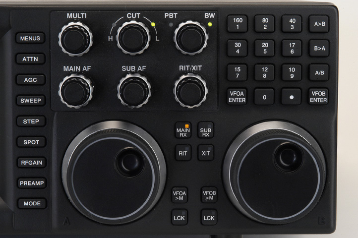
Figure 4. ORION front panel, right side

Figure 5. ORION rear panel

Figure 6. ORION rear panel, left side
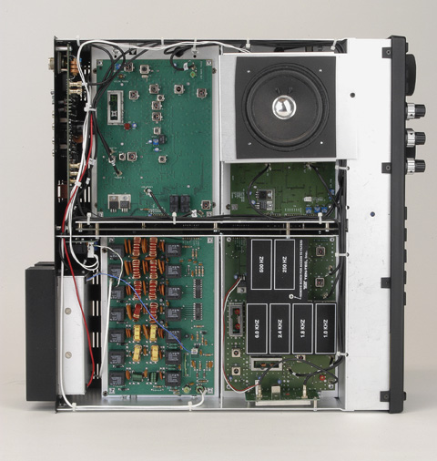
Figure 7. ORION top view, cover off

Figure 8. ORION bottom view, cover off. The open space at left rear is for the optional automatic antenna tuner, not installed in this display unit.
.bmp images of the ORION screen and
descriptions are below.

Figure 9. ORION main screen shot
Shown above is the ORION default screen, with the band scope turned off. This is how the display on ORION typically looks when the radio is in use, band scope off, no menu presently selected. The words and numbers surrounding the screen (off, 100, 50, etc.) correspond to various settings for controls operated by buttons and/or knobs on the transceiver (see closeup of front panel picture above for button labeling).
Icons on the screen: The TR label next to the VFO A frequency display corresponds to transmitter (T) and main receiver (R) being assigned to that frequency. This display in controlled by the matrix of 12 buttons to the ORION's far left side under the S-meter. A third label (S) for subreceiver will also appear. If the subreceiver is not turned on, no (S) marker appears on the screen - as not shown here.
The bargraph to the immediate right of the VFO B frequency display is the subreceiver S-meter. The subreceiver S-meter is both bargraph and numerical display (like 'S8') above the bargraph. As the subreceiver is off in this example, no value is indicated. Main receiver S-metering is done on the large analog meter.
The icons shown that look like a small speaker and a pair of headphones next to the mode and bandwidth values for each receiver indicate where audio is being delivered. In this case, audio from both receivers is being sent to the speaker (as a speaker icon is shown for both) and audio for both receivers appears in both headphones, as indicated by two pairs of 'ears' next to each receiver display.

Figure 10. AUDIO menu selections
To adjust the audio output via the headphones or speaker, there is a pop-up menu that is brought to the screen by pressing the AUDIO button on the front panel. The seven buttons that line the right side of the radio immediately next to the screen are then used to control audio functions.
The first two menu items are Left: and Right: - this determines what receiver's audio is sent to which earphone on your headset. As you can see, presently the left earphone is set to "Main" and the icon by the main receiver mode and bandwidth display shows a 'left earpiece' only. The third menu item is Spkr: - in this case, audio for both receivers is being delivered to the speaker. Two speaker icons are shown on the screen (the subreceiver speaker icon is partially obscured by the menu).
Audio menu item #4 is BinRX: - this is to turn the ORION Panoramic Stereo receive feature. Downloadable sample .WAV files and a complete description of the mode are available at the ORION main page.
The last three items on the audio menu are TX EQ, RX EQ, and SUBEQ. These controls enable tailoring audio frequency response for greater effectiveness and to accomodate operator preferences. TX EQ effects range (in 1-dB steps) from high pitched at -20 dB to essentially flat response at zero dB to very bassy at +20 dB. The same curves apply to the main receiver equalizer (RX EQ) and the subreceiver equalizer (SUBEQ). The displayed setting of the equalizers refers to the amplitude in dB (at about 100 Hz) relative to the highest frequency in the passband. For example, the -20 dB setting show -20 dB at 100 Hz relative to 0 dB at 6 kHz. There are response curves for these shown in the SPECIFICATIONS section on the bottom of the main ORION web page.

Figure 11. Transmit menu
There are several menus, organized by type, embedded into ORION. By pressing the MENU button, one of seven menus will appear on the screen. Each of the seven menus are selected after pressing the corresponding button along the right side of the radio immediately adjacent to the screen. Shown above is the TX menu. TX is highlighted to the right side of the screen.
If the ORION is equipped with an automatic antenna tuner, it can be bypassed by turning it off in the TX menu as shown. The ORION transmitter can be turned off. Keying loop 1 and 2 are the full break-in linear amplifier keying loops. Two linear amplifiers can be simultaneously connected to ORION. For non-break in amps, the EXT T/R Delay controls are used for keying either amp #1 or amp #2. "Transverter" refers to routing a low level transmit signal out to the rear panel transverter jack.
ORION can remember your antenna preferences by band. With the two antenna connectors, you can have ORION recall the proper antenna when you change bands with the band change keypad. Have '10M Antenna' set to ANT 1 - every time you change to 10 meters, ANT 1 is switched in. The dashed line shown above means no antenna assignment, and changing to that particular band will leave connected whatever antenna you are using at the time of the band change.

Figure 12. CW transmit menu
Shown above is the CW TX menu. One of the unique features of the ORION is allowing the operator to adjust the CW transmit rise and fall times for either a harder or softer edge to taste. The rise/fall is adjustable with the front panel MULTI knob and is selectable from 3 mS to 10 mS. See Doug Smith's technical description of proper CW keying waveform ("Occupied Bandwidth of CW Emissions") as related to the ORION by clicking here.
QSK delay is adjustable. There are three possibilities for keying CW with the ORION - using a straight key or bug (non-keyer device), a paddle for the rigs' internal keyer, or having both a paddle connected to the rig and an external device or keyer keying the rig at the same time. There are two CW jacks on the radio, one on the front and one on the rear. They are wired in parallel. Whatever selection is made in the CW menu, both jacks correspond to.
It is not unusual to want to have a paddle connected to the radio while having the radio key CW from an external device (like the output from contest software on a computer). In this case, set the internal keyer to 'On' and plug in a paddle to use the internal keyer. One of the DIN connectors on the rear panel has a PTT connection that can accept CW keying input (even for full QSK). Connect your external keyer output to the PTT connection and then you can use either the internal keyer or an external keying device at the same time. In the ORION packing kit, we provide you with a cable that converts the DIN connector to standard RCA-style phono connectors to make this connection a snap.
CW weighting is adjustable.
Variable sidetone pitch has autotracking CW offset. This can be set to a value of 300-1200 Hz in 20 Hz steps to suit operator taste. The CW offset automatically tracks whatever value the sidetone is adjusted to.

Figure 13. VOX menu
Fairly self-explanatory. VOX trip, hang, and anti-VOX levels are easily set using this menu and the MULTI knob.

Figure 14. Receiver control option menu
The receiver control option menu. This is where it really starts to get interesting. First, the selectable SWEEP range. The front panel sweep scope is continuously updating on the main receiver when turned on. There are 5 selectable sweep ranges available at 4.5, 9, 18, 36, and 72 kHz. Whatever selection is chosen displays "X" kHz of active bandwidth on the sweep scope.
Ever felt like your rig's 'fast' AGC was too fast, or too slow? That 'medium' could be quicker? Another unique feature of ORION is allowing the user to program AGC response time rather than being confined to the traditional settings of OFF, SLOW, MED, and FAST. These traditional settings are available. Adapted from our high-end commercial receiver, the RX-340, programmable AGC allows each receiver can be set up to have its own AGC characteristic to suit operator taste. Hang, decay and threshold are all fully adjustable, giving the user literally hundreds of thousands of possible AGC characteristics to select from.
PBT and bandwidth tracking: Each receiver has its own set of 591 IF-DSP bandwidth filters, that are independently adjustable per receiver. However, it may be useful to be able to adjust the filtering and passband tuning controls on each receiver in tandem. BW Track and PBT Track allow the ORION operator to adjust the bandwidth and/or PBT controls simultaneously on each receiver by turning one knob if the control is selected. Track can be enabled for neither, both, or either the BW or PBT controls.
Hardware noise blanker: ORION is equipped with two noise blankers. One is a DSP NB, that is controllable from the front panel. The second is an analog noise blanker, selectable on/off from the menu system. The DSP and analog noise blankers can be used alone or in tandem.
Squelch threshold is selectable per receiver.
The BW and PBT controls on the front of ORION are selectable to tune in three steps, by 10 Hz, 50 Hz, or 100 Hz.

Figure 15. OTHER control menu

Figure 16. Model 302R remote encoder/keypad
The model 302R remote encoder/keypad allows control of a number of functions on the ORION transceiver. Connects to the rear panel REMOTE jack via a 6 foot cable.
Many transceiver functions can be controlled from the three buttons marked F1 F2 and F3 above the remote tuning pod knob. The first three menu items are the assignable functions for each F button. They are: Switch VFO A/B, step size, mode, turn sweep on/off, emulate the USER 1 - USER 2 - SEND 1 - SEND 2 - SEND 3 buttons on the front panel.
Rem Pod Enter: Refers to the VFO that direct frequency entry is sent to. The default for the keypad on the 302R is to act as if it were a duplicate of the band change keypad on ORION. Press '7' and the rig goes to 160m, '8' for 80m, '9' for 40m. For direct frequency entry, press E then enter the desired direct frequency.
Menu Delay inserts a slight delay between the time you press the MENU button and when the radio switches to menu control on the screen.
Contrast is for screen and lettering contrast on the screen.
The various RATE controls allow each of the two main tuning encoders on the radio, the remote pod encoder, and the RIT to be adjusted for kHz per revolution. This is separate from step size selections.
There is one additional function on the OTHER menu not shown in the .bmp in Figure 15 called Black/White. This allows the ORION screen to be reversed so it appears as white lettering and numbering on a black background if desired.

Figure 17. SSB transmit menu
AUX input gain allows compensation for high or low audio levels delivered to the ORION's rear panel AUX I/O connector.
TX filter bandwidth: There are 18 selectable SSB transmit bandwidths from 900 to 3900 Hz selectable with ORION.
LF Rolloff: Low frequency rolloff allows the operator to cutoff the low frequency response of the SSB transmit signal. Using a microphone with excessive bass response, a bassy operator voice and high SSB transmit bandwidth can result in excessive low end response on an SSB TX signal. To decrease the low end response, the audio frequencies on transmit can be rolled off past a certain point, selectable here.
TX audio source enables input from either the microphone jack, the rear panel AUX I/O connector, or both at the same time.

Figure 18. Filter menu.
ORION is different from other HF transceivers specifically because we are utilizing crystal filters as roofing filters within the transceiver. These are not to be confused with traditional BANDWIDTH crystal filters as have been used in HF transceivers for many years. Selectable roofing filters allow the transceiver to reject any unwanted signals outside the target frequency that will have a negative impact on receiver performance. One downfall of "DSP" radios built by other manufacturers is specifically their utilization of a 15 to 20 kHz wide roofing filter that allows undesired signals close to the target frequency to compromise receiver performance. See our comparative receiver chart on the main ORION page for examples of the amazing difference it makes!
Roofing filter selection in the ORION is either automatic or manual. By setting I.F. Selection to "Auto", as you cross the threshold of each roofing filter bandwidth by turning the BW encoder, the roofing filter automatically comes into use. For example: the stock 2.4 and 1 kHz roofing filters, used in CW mode. As the BW control for the DSP filters is tuned from 2410 Hz to 2400 Hz, the 2.4 kHz roofing filter automatically is switched in line. As the operator crosses 1010 Hz to 1000 Hz, the 1 kHz roofing filter automatically is switched in line. And so on for the optional 1.8 kHz, 500 Hz, and 250 Hz roofing filters if installed.
Our philosophy has always been that the operator should have full control over the receiver. So, if you'd like de-optimize receiver performance, we say, go right ahead! You can manually select the desired roofing filter for any of the available bandwidths (stock: 15 kHz, 6 kHz, 2.4 kHz, 1 kHz) or optional (1.8 kHz, 500 Hz, 250 Hz) and have that filter always be in line regardless of where the DSP filter bandwidth is set.
The "Enable" settings for the 1.8, 500, and 250 filters instruct the ORION that a particular roofing filter is installed. This control can also be used to temporarily disable an installed roofing filter while allowing other installed ones to be used (again, in step with our receiver/operator control philosophy). CF adjustment is for DSP compensation for variations in filter frequency tolerances.