 Douglas
T. Smith Editorial Services
Douglas
T. Smith Editorial Services m 32-Bit DSP: A Digital Radio Performance Advantage?
|
| 32-Bit
DSP: A Digital Radio Performance Advantage? © 2002, Douglas T. Smith Editorial Services www.doug-smith.net Preface Digital signal processing (DSP) hardware has advanced to the point where 32-bit floating-point computing power may be embedded in radio transceivers. In the Ten-Tec 565 Orion, more than one 32-bit DSP is included. When signals are digitized using 24-bit resolution or less, though, is 32-bit processing really necessary? Or is it just marketing hype? Well, no! It's not just hype. Follow me through a brief discussion of how numbers are handled inside a DSP and see for yourself why 32-bit floating-point processing represents a real improvement in IF-DSP transceivers. Fixed-Point vs. Floating-Point DSPs work with binary or base-two numbers. A certain collection of binary digits or bits is used to store and manipulate numbers. We usually characterize a particular DSP primarily by the number of bits used; that is, 8-bit, 16-bit or 32-bit. In the case of a 32-bit DSP, those 32 bits may be allocated in a variety of ways to represent numbers. Two popular representations dominate the scene: fixed-point and floating-point. Let's take a look at those formats along with some of their advantages and disadvantages. Fixed-Point Format In fixed-point representation, a binary number is understood to be in signed-fractional format. Signed means that the number can be either positive or negative. Fractional means that a number n is interpreted to fall within the range -1 = n < 1. In this format, the most-significant bit denotes the sign of the number. See Fig 1. When the sign bit is 0, the number is positive; when the sign bit is 1, the number is negative. The separation between the sign bit and the rest of the number is known as the radix point. In base 10, the radix point is called the decimal point, but we cannot call it that in base two! 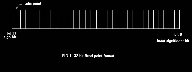 Half the possible numbers are positive and the other half negative, therefore. To make DSP computations convenient in fixed-point notation, negative numbers are stored in two's-complement form. You get the two's complement of a number after you subtract it from zero. Taking some 8-bit examples, 1000 00002 is the most-negative number and 0111 11112 is the largest positive number. Two's-complement notation is convenient in DSP because numbers may be added, subtracted, multiplied or divided in straight binary fashion while preserving the sign of the result. The addition or subtraction of two fixed-point numbers falling in the given range may produce a result outside that range, though. Such a result, called overflow, must be either avoided or corrected during DSP calculations. The need to avoid overflow tends to lead to scaling of data (reducing the absolute value of numbers). Data scaling reduces the range of numbers that can be represented: dynamic range. Multiplication of two numbers in fixed-point notation is convenient because the product of two such numbers is guaranteed also to fall within the input range. Overflow is not a problem for multiplication, a very common operation in most DSP algorithms; however, the product of two numbers, each of length b bits, has length 2b. That is, multiply two 16-bit numbers and you get a 32-bit product. A 16-bit DSP has only 16 bits to store the result, so the 32-bit product must be either truncated or rounded to fit in the available space. Truncation is simply the process of chopping off the least-significant bits that don't fit. That naturally introduces a small error in the stored result. For both positive and negative fixed-point numbers, the error is always negative. Such a negative bias may grow throughout successive calculations. A better way of eliminating the extra bits is convergent rounding. In convergent rounding, a number equal to half the least-significant bit to be kept is added prior to truncation. In that way, the resulting error is just as likely to be positive as negative and it doesn't grow out of control with subsequent calculations. But errors are just as likely to be small as large. Since they also may be either positive or negative, the errors over time produce quantization noise. Such noise sets the lower limit of the dynamic range of calculations in a DSP. Small signals that only exercise a few bits may get lost in that noise because of rounding or truncation errors. Analog-to-digital converters (ADCs) normally deliver data to DSPs in fixed-point format. They suffer from quantization noise of their own because they have a fixed number of bits available. Designers want the ADC to be the limiting factor in the final performance of systems, so it is generally beneficial to use more bits during calculations than the number of bits used to represent numbers. Floating-Point Format Floating-point format greatly extends the range of numbers that can be represented. It does that by separating numbers into two parts. The first part, called the mantissa, denotes a signed fraction, just as in fixed-point format. The second part, called the characteristic or exponent, signifies the scale of the number. See Fig 2. The exponent is usually stored as a signed integer so that mantissa m and characteristic c form a number that is understood to be (2c) m. 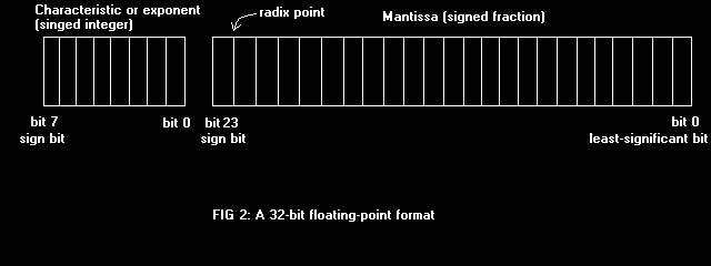 It is possible to allocate storage bits between m and c so that computational dynamic range is vastly extended over what is possible with fixed-point notation. It might seem at first that handling numbers in two parts is inherently slower than handling them in one part. Multiplying two floating-point numbers, for example, involves multiplying the mantissas and making a possible adjustment to the characteristic. Adding two floating-point numbers involves adjusting them to a common scale, doing the addition, and then readjusting the characteristic. In actual fact, floating-point DSPs are designed to overcome this apparent limitation by employing sophisticated arithmetic processing units. Computationally intensive tasks such as filtering and noise reduction may therefore benefit from the increased dynamic range of floating-point. Preserving Dynamic Range A major goal of digital transceiver design is to obtain the highest dynamic range possible in the DSP section. That eases the requirements of preceding analog stages.1 Having obtained samples of an IF signal in a receiver, for example, the idea is to preserve the signal-to-noise ratio (SNR) of that signal until it is demodulated and delivered to the user. 32-bit processing makes that goal a lot easier to achieve. 32-bit DSPs, such as those in the Ten-Tec Orion, may incorporate accumulators of up to 80 bits in length so that rounding occurs only after lengthy series of multiplications and additions have finished. One outstanding reason for using DSP in radio gear is its ability to produce very sharp and well-behaved filters. A type of DSP filter called a finite impulse response (FIR) filter is very popular because it has a simple structure and exhibits a linear phase delay. Linear phase delay is good for data communications because it minimizes inter-symbol interference that sometimes occurs with regular analog filters. The output of an FIR filter2 is the sum of the products of some input data samples, xt, and a series of coefficients, ht. At each sample time, input samples are shifted to the right by one location and the multiply-and-accumulate (MAC) operation produces a new output value. Programmers will recognize this as a buffer. Coefficients are fixed in value and position, and don't shift. The number of coefficients, L, is known as the length of the filter. The set of coefficients determines the frequency response of the filter. In general, sharp filters require a large number of coefficients: Filters having as many as 200 are common. Again, only a fixed number of bits is available to represent those coefficients. That introduces an error between the desired frequency response and the actual response. Truncation or rounding of input and output data adds quantization noise to the filter's output, but doesn't affect the frequency response. On the other hand, truncation or rounding of the filter coefficients affects the frequency response but doesn't add noise to the output. Filters are normally designed on desktop computers using floating-point notation with 12 or more significant decimal digits in the mantissa. Embedded DSP systems that achieve 32-bit accuracy or less cannot reproduce filter coefficients quite that exactly, so some error occurs. A DSP designer is concerned with how coefficient inaccuracy affects the shape and ultimate attenuation of his filter-- that is, how much rejection of unwanted signals he will get from his design. If a particular receiver design, including the ADC, were capable of 100 dB of dynamic range, then it would follow that filters reaching 100 dB of ultimate attenuation would be required to preserve dynamic range. It turns out that 16-bit coefficients cannot do that and at least 24 bits are necessary. In a radio such as the Orion, 24-bit data and 32-bit coefficients are used, producing interim products of 56 bits in length. By the time 200 or more of those are added, the result grows by several more orders of binary magnitude. 64 bits would be an acceptable length for the filter's final accumulator in that case; but it is convenient to just use 32-bit data and coefficients, which means an 80-bit accumulator is ample to accommodate the addition of many 64-bit products. Another reason for conducting computations with extended bit precision arises in AM and FM demodulation and in speech processing. DSP algorithms used for those functions often involve the taking of square roots. Now the square root of a 48-bit number is a 24-bit number. If 24-bit accuracy were to be preserved in the result of a square-root calculation, then the input argument would have to be at least 48 bits in length. 32-bit DSPs can handle the extended precision at least twice as fast as can a 16-bit processor. Execution Speed 32-bit DSPs can pump a lot of data. It isn't hard to see that handling data 32 bits at a time is at least twice as fast as handling them 16 at a time. That increased execution speed allows designers to incorporate more advanced features in their designs. Digital transceivers run code that is often written in assembly language, or the native language of the processor in use. Filtering, speech processing and other algorithms must complete their computations in the time between input samples. When the sampled signal is at an IF of, say, 14 kHz, the sampling frequency might be four times that, or 56 kHz. That leaves less than 20 µs between samples for some very intense calculations. The current crop of floating-point DSPs is optimized for the type of number-crunching common in radio communications. Analog Devices SHARC DSPs, for example, complete one MAC operation in a single cycle. Such devices hum along at 60 MHz or more so that a performance level of 60 megaMACs is achieved. That is the kind of awesome computing power that just a few years ago was only dreamed of. Conclusion I've outlined a few of the reasons that 32-bit floating-point DSPs are finding their way into state-of-the-art transceivers like the Orion. Perhaps you can appreciate the amount of effort that has gone into producing them, programming them and the immense variety of applications to which they apply. DSP has changed the world for good. What did we ever do without it?-- Doug Smith, KF6DX Notes:
|