This is an old revision of the document!
30 meter mod for the Omni D
References
- Tentec's WARC band mod instructions warc_install.pdf
Introduction
The World Administrative Radio Conference approved the WARC bands at nearly the same time as Tentec developed the Omni 545 and 546 - 1979. The original Omni series came with 10.0-10.5 MHz receive only. A kit was later offered to upgrade the series to 10.1 MHz (30 meters) transmit and 24.89 MHz (12 meters) receive and transmit. As of this writing (2017), the kit has been unavailable for some time. 18.068 MHz (17 meters) was not offered, because it was a multiple of the Omni's 9 MHz carrier oscillator, and would have had unacceptable spurious output.
This mod is a partial duplication of the WARC kit, for 30 meters only. Tentec encouraged amateurs to perform this mod themselves in the kit instructions. However, as parts are no longer available from Tentec, substitutes were developed. Omni owners contemplating this mod should see the instructions at warc_install.pdf to familiarize themselves with the steps. In particular, the steps listed under the heading "SUBJECT: Modification to permit operation on 10 MHz band only" should be read. The disassembly information given there will not be repeated here. The mod is "no tune", so no alignment is necessary.
Parts list
- 3x - Type T50-6 powdered iron toroid cores
- 4x - 56 pF, 50V, C0G/NP0, radial leaded ceramic capacitors
- 1x - 270 pF, 1000V, radial leaded ceramic capacitor
- 1x - 330 pF, 1000V, radial leaded ceramic capacitor
- 1x - 560 pF, 1000V, radial leaded ceramic capacitor
- about 45 inches - #18 magnet wire
- about 40 inches - #24 magnet wire
- about 40 inches - #32 magnet wire
Theory of operation
A 9 MHz carrier oscillator is produced on the SSB generator board. It is modulated with signal information - SSB audio or on/off keying for CW. For the 10 MHz band, VFO output varies from 18.99 to 19.49 MHz. This is mixed with the carrier oscillator on the TX mixer board, producing two outputs: the desired signal from 9.99 to 10.49 MHz, and an image at 27.99 to 28.49 MHz. The 28 MHz image is removed by a tuned filter on the bandpass filter board before proceeding to the low-level driver board and the power amplifier board. All amplifiers produce some harmonic distortion, and these harmonics (multiples of the output frequency) are stripped off by a lowpass filter on the lowpass filter board before reaching the antenna output.
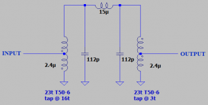
Tentec used tuned transformers for the bandpass filters, which featured very light coupling between the two coils. These formed "double tuned, over-coupled bandpass" filters, a wide bandwidth type of filter. The only concerns at 10 Mhz were removal of the 28 Mhz image generated in the TX mixer, and perhaps any remaining VFO energy at 19 MHz which found its way out of the mixer. A tight filter was not required. This is approximated here by a double-tuned, inductor-coupled bandpass filter formed on three toroid cores. It, like those used by Tentec, has a relatively wide passband, 2 MHz wide.
Tentec used standard LC lowpass filters at the power amplifier output, and that filter for 10 MHz is approximately reproduced here.
Performing the mod
Building the bandpass filter
Adding the bandpass filter to the board
Adding the lowpass filter to the board
Testing
Click any image for an enlarged view.
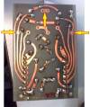
Bandpass board, bottom side, showing pads for 30m mod: 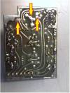
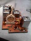
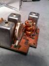
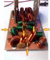
Bandpass board, top side, showing finished 30m filter mod (between bandswitch and the shield can at the right): 