Ten-Tec's
Orion HF Transceiver: The
New Performance Standard
© 2002, Douglas T. Smith Editorial Services
www.doug-smith.net
(Updated 2-22-2003)
Introduction
In the last decade of the 20th
century, digital signal processing (DSP) enabled
a leap in the performance-to-price ratio of
transceivers of all kinds. Yet some early DSP
rigs expose some of the drawbacks of then-current
technology: mediocre dynamic range, lack of
processing speed for advanced algorithms and poor
spurious response. Many agree that the bells and
whistles in a transceiver design are fine, but
traditional measures of performance separate the
mice from the men.
Today, hardware capabilities have nearly caught
up with theoretical advances in DSP, making
possible what was not even dreamed five years ago.
Many of us technical types tend to dote on the
receiver dynamic range issue because it places
the harshest performance demands on DSP systems.
This discussion of the design philosophy and
execution of the Ten-Tec Orion shall therefore
begin with its receivers.
At the block-diagram level, we first look at the
Orion's analog hardware to examine interplay with
its digital section. Performance limitations and
trade-offs are emphasized. Next, we scrutinize
DSP hardware for its contribution to system
response. Finally, we take a peek at some DSP
algorithms at work inside the Orion-- both in
transmit and receive-- that reveal certain
innovations and a level of performance previously
unattained by any HF Amateur Radio transceiver,
bar none.
Orion's Analog Front End: Two Independent
Receivers
Refer to the block diagram of Fig 1. It shows
how the antenna selection matrix of the Orion
connects any of three antennas to the main and
sub receivers-- that's right! The Orion has two
independent receivers. The main receiver covers
the ham bands only and the sub receiver is
general-coverage. Unlike other rigs, no
restrictions are placed on the frequency
separation between the receivers. The two
receivers may be tuned together or separately.
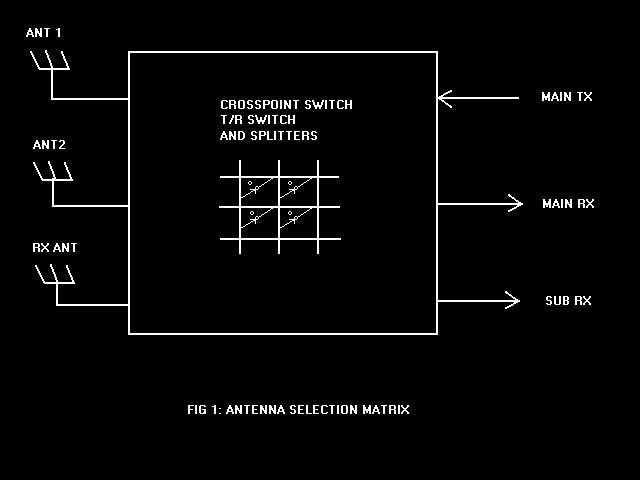
You can use one antenna for transmit, another for
the main receiver and yet another for the sub
receiver; or you can command the unit to use one
antenna for everything. Flexibility is one key
precept in the Orion's design; performance is the
other.
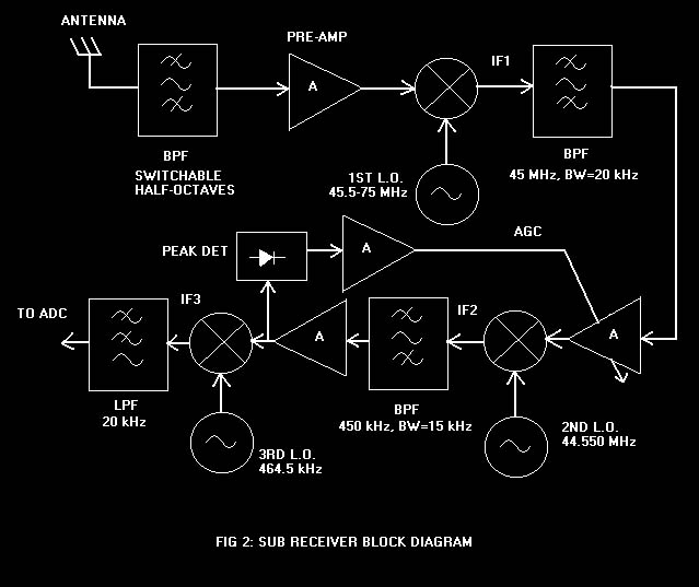
Now look at Fig 2. The sub receiver is a Jupiter-like
design with RF preselection, a pre-amp and an
attenuator. It converts signals to a 45-MHz 1st
IF, where a 15-kHz-bandwidth crystal filter
provides initial selectivity. The 2nd
IF is at 450 kHz, where much of the gain and some
additional selectivity lie. The last conversion
is to a 3rd IF of about 14 kHz. This
is where a 24-bit, high-performance analog-to-digital
converter (ADC) digitizes signals.
The main receiver also uses RF preselection. See
Fig 3. Its preselectors are optimized for ham-band
coverage; thus, they are much narrower band-pass
filters (BPFs) than those of the sub receiver. A
pre-amp and step attenuator are also included.
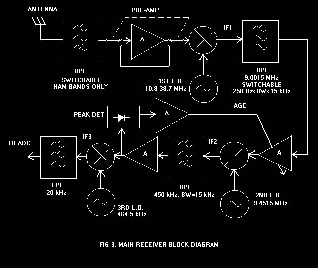
A high-level JFET mixer is employed. An amplifier
is used at the local-oscillator (LO) port to
reduce the LO level coming from the synthesizer
itself. The entire front end achieves outstanding
dynamic range, as described more fully below.
The main receiver's 1st IF is located
at 9 MHz. You may be asking, "Why not up-convert
in this high-performance design?" Well, one
reason is to go directly to an IF where sharp
crystal filters are possible. Conversion to VHF
and then back down would involve another local
oscillator (LO). A plurality of LOs in a receiver
tends to increase the number of unwanted signals
or "birdies" in it. In addition, many
Omni-VI users already have 9-MHz filters that are
fully compatible with the Orion. When they
upgrade their stations, they may want to transfer
their filters to their new transceiver.
The main receiver converts 9-MHz signals to 450
kHz, then to 14 kHz, much like the sub receiver.
Commonality of last IFs means that the digital
sections of the two receivers are identical,
achieving cost savings and enabling identical DSP
features on both.
Synthesizers
The Orion's two receivers are coherent in
that a single frequency reference is used. It is
a temperature-compensated crystal oscillator (TCXO)
that drives both the sub receiver's phase-locked
loop (PLL) and the main receiver's direct digital
synthesis (DDS) LO. The sub receiver employs a
standard PLL synthesizer, moving in 2.5-kHz steps.
Fine-tuning to 1 Hz is achieved in DSP software
through complex mixing, described further below.
The main receiver's synthesizer is a state-of-the-art,
DDS-driven PLL with final frequency division. See
Fig 4. At the heart of it is a PLL running at UHF--
roughly 400-500 MHz. The PLL's output frequency
is set by the reference frequency provided by a
high-performance DDS. This technique has the
advantage of very low phase noise. Phase noise is
the unwanted phase modulation of circuit elements
by thermal noise. The Ten-Tec method exhibits
very high tuning speed and suppression of
spurious DDS outputs outside the loop bandwidth.
The PLL also tends to lower phase noise inside
the loop bandwidth.
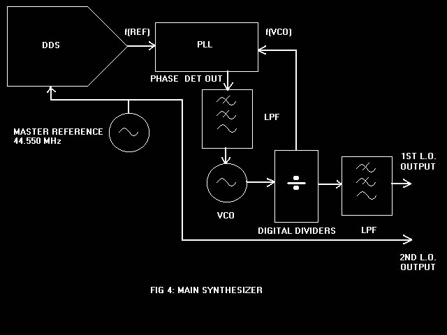
The UHF output is divided downward in frequency
using high-speed dividers. Frequency division
produces further improvement in phase noise
performance-- by 6 dB per octave (factor of two).
Since this LO runs at the RF plus 9 MHz, its
range is 10.8-38.7 MHz over the RF range 1.8-29.7
MHz. A final division ratio of more than 10 means
a further reduction in phase noise of about 20
dB, as limited by divider noise.
Performance is unmatched-- about -140 dBc/Hz--
right down to frequency separations of less than
1 kHz! Extremely low phase noise means freedom
from reciprocal mixing-- the unwanted mixing of
LO noise sidebands with adjacent signals. The
main synthesizer also drives the transmitter so
that your signal will be the cleanest on the
bands.
Analog Meets DSP, Object: Matrimony
In addition to its retinue of DSP filters,
the Orion comes equipped with four crystal
filters in its 9-MHz IF as standard. Their
bandwidths are 20, 6.0, 2.4 and 1.0 kHz. Optional
crystal filters having bandwidths of 1.8 kHz, 500
Hz and 250 Hz are available. Both four- and eight-pole
designs may be obtained. Why did Ten-Tec do this?
The answer comes in a discussion of receiver
dynamic range. Dynamic range may be defined as
the ratio of the smallest usable signal to the
largest tolerable signal. It is useful to
consider the case wherein a small desired signal
must be copied in the presence of a large
undesired signal. Where analog meets DSP, that
situation is central to the discussion.
DSP and Receiver Dynamic Range
For bandwidths of interest, the DSP section
of the Orion achieves 100 dB of spurious-free
dynamic range (SFDR). That means small desired
signals can be copied in the presence of large
undesired signals on adjacent frequencies without
much analog filtering. It also means that analog
automatic gain control (AGC) does not have to be
used until signals reach S9+35 dB. 100 dB is a
lot-- it is a power ratio of 10 billion!
With such great signal-handling capabilities, it
might seem as if crystal filters would be
superfluous; but for the ultimate in performance,
analog selectivity cannot be beaten. That is why
Ten-Tec included crystal filters in the Orion.
You get all the benefits of razor-sharp DSP
filters with shape factors as low as 1.05:1 as
well as the advantages of eight-pole crystal
filtering if you want them. This architecture
removes any doubt about your ability to pull out
the weak ones during crowded band conditions.
A few traits of the analog section of the Orion
speak to other measures of dynamic range, such as
intermodulation distortion (IMD) and phase noise.
Since data converters in the DSP section do not
contribute significantly to IMD (they are quite
linear), performance is primarily determined by
analog electronics. 2nd- and 3rd-order
intercept points (IP2 and IP3) are commonly
accepted measures of IMD response in receivers.
The Orion exhibits an IP3 of +25 dBm and an IP2
of +78 dBm at standard frequency spacings. One
astonishing result of the use of crystal filters
in the Orion is that IP3=+25 dBm is maintained
right down to spacings of 5 kHz and less! That is
the best you can get off the shelf. Contesters
know that this kind of performance may be what
makes or breaks their efforts during crowded
conditions. The Orion advantage is plain.
Narrow analog filters can do nothing to mitigate
reciprocal mixing. That effect appears as the sum
of the LO noise powers of both transmitter and
receiver LOs. If a transmitting station has poor
phase-noise performance, some of the energy from
its noise sidebands may appear in your passband
when other adjacent signals are present, even if
your synthesizer is perfect. As against that, we
can state that the superb phase-noise performance
of the Orion minimizes such interference to and
from other stations.
IP3 is usually measured at frequency separations
of 20 kHz or so. When you get down to spacings of
5 kHz or less, both interfering signals lie
within the "roofing" filter of the
receiver. Both tones are passed along to
subsequent analog circuits. Of concern is
receiver performance when two tones are inside
the final passband. Such in-band IMD tests must
be conducted with AGC optimized for the signals
of interest.
For example, two closely spaced, on-channel tones
may be introduced to a receiver and the IMD
measured. AGC, whether digital or analog, must be
set to it slowest setting so that it does not
follow the envelope of the signal. Under these
conditions, a receiver must exhibit low IMD for
signal levels normally encountered on the ham
bands. It should not add to IMD created by the
transmitter, which is typically 30-40 dB below
PEP for two-tone conditions.
Off-channel signal levels of up to -23 dBm (50 dB
over S-9) must often be tolerated without
significant IMD in analog sections of a receiver.
Let us examine what performance demands are
thereby placed on the IP3 performance of
receivers.
The IP3 of a receiver that can handle 50 dB over
S-9 from each of two adjacent-channel signals
without perceptibly affecting on-channel
performance depends on the receiver. Let us say
that a receiver has a noise-floor power of -126
dBm (about 0.1 µV) in a 2.4-kHz bandwidth. That
says that a signal at -126 dBm produces a power
just equal to that of the noise floor. If then,
in the presence of two -23 dBm off-channel
signals, a receiver produced an in-band, 3rd-order
IMD signal equivalent to -126 dBm, the IP3 would
be (126-23)/2-23=+28.5 dBm. IP3 is usually
measured well above the noise floor instead of at
the noise floor, but this example shows roughly
how it is done.
What does all that mean? Well, it means that two
50-dB-over-S-9 signals on adjacent frequencies
would produce a barely audible IMD signal. Not
bad, eh? That assumes that the interfering
signals themselves have negligible IMD and phase
noise and that is often an unjustified assumption.
Nonetheless, the IMD3 dynamic range would be 126-23=103
dB.
Therein lies the beauty of the Orion design. Its
IMD dynamic range numbers are unexcelled-- the
unit maintains those numbers down to very small
frequency separations by virtue of its crystal
filters.
IF-DSP Dynamic Range
DSP dynamic range is very important because
of the situation previously described, wherein a
strong adjacent-channel signal appears
simultaneously with a small, desired signal. What
you can hear in a DSP receiver is determined by
what signals DSP can digitize. If a large, off-channel
signal appears that forces the electronics to
reduce gain so that the ADC is not overloaded,
weak, on-channel signals no longer have enough
gain to be copied.
ADC overload can never be allowed to occur
because when that happens, signals are
irrevocably corrupted. Signals that are larger
than the full-scale range of the ADC must force
reduction of gain in the analog section of the
receiver. So both analog and digital AGCs are
used in the Orion. Resort to analog AGC only need
be made when signals inside the roofing bandwidth
exceed about S-9 plus 30 dB. At that point,
sensitivity is reduced but what we are
discovering is that phase-noise performance-- as
determined by reciprocal-mixing measurements--
already limits what you can hear. So performance
is phase-noise limited and not DSP limited. Even
so, the Orion gives you the option of kicking in
a crystal filter, preventing movement of the
analog AGC and the sensitivity reduction
described above.
IF-DSP dynamic range also comes into play in the
transmitter. SNR and opposite-sideband rejection
are largely determined by the bit-resolution of
DSP elements. 24-bit data conversion and
subsequent 32-bit processing assure excellent
performance.
DSP Algorithms
The Orion's DSP algorithms use what are
called analytic signals. An analytic signal
actually consists of a pair of signals: an in-phase
(I) and a quadrature (Q) signal. Signals I and Q
maintain a constant 90° phase relationship to
one another, no matter the frequencies of the
signals. Those are taken together to perform
complex mathematics that can modulate and
demodulate virtually any type of signal. For SSB,
we still call it the phasing method.
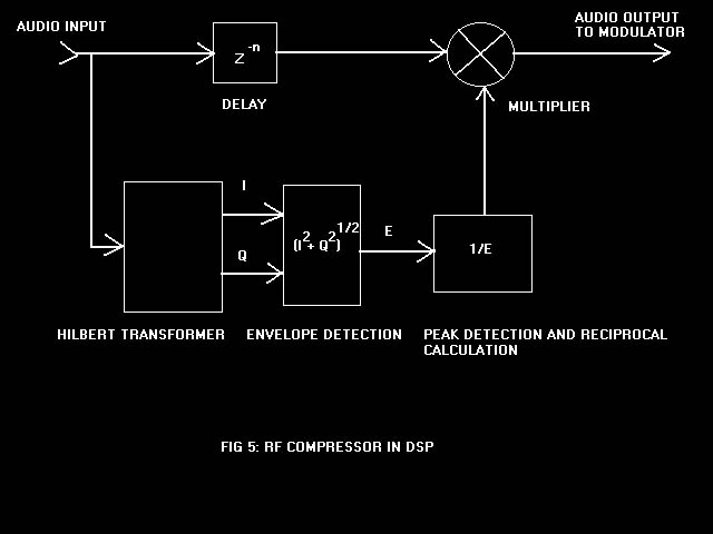
The flexibility of analytic signals extends to
many parts of a transceiver's job. For example, a
signal's RF envelope may be computed as (I2+Q2)1/2.
This can be used directly to demodulate AM in a
receiver, or to employ an RF compressor in a
transmitter.
Transmit Speech Processing in DSP
It might seem funny but in a DSP transmitter,
it is relatively easy to compute the
transmitter's RF envelope before the modulation
is even performed! That, in turn, makes it
possible to preprocess the audio applied to the
modulator to get exactly the same effect as that
produced by an RF compressor. See Fig 5. Post-modulation
band-pass filtering maintains the desired
occupied bandwidth. As the decay time of the
compressor is decreased, an RF compressor
approaches the behavior of an RF clipper, long
known to be the most effective form of speech
processing for SSB. In combination with the
Orion's transmit equalizer, results are quite
dramatic.
The reason RF compressors and clippers are so
effective is that they increase the average power
transmitted. Human voices tend to have high peak-to-average
power ratios-- as high as 15 dB. That means a
transmitter whose peak envelope power is limited
to 100 W may achieve an average power of as
little as 3 W. Under such conditions, the Orion's
RF compressor may add 10 dB or more to the
average power, equivalent to a ten-fold increase
in output power. The speech processor achieves
this goal without introducing the kind of
distortion that harms intelligibility, such as
that created by heavy audio compression or
clipping.
Audio Equalization and Speech Monitor
The Orion sports audio equalizers in both
transmit and receive. The equalizers are similar
to tone controls in that they alter frequency
response to favor either high or low audio
frequencies. Response may be adjusted up to 6 dB
per octave (factor of two) in either direction.
The transmit equalizer helps you get the best
sound from whatever microphone you connect to the
Orion. It is also key in productive use of the
speech processor. While most of the energy in
human speech lies at low frequencies, relatively
high frequencies carry much of the intelligence.
Cutting the lows and applying the speech
processor makes phone signals much easier to copy.
Orion achieves low-frequency response to 50 Hz
without compromising opposite-sideband rejection.
Maximum transmit bandwidth is 3900 Hz.
Orion's speech monitor allows you to monitor your
transmitted signal. What you hear is the signal
as actually transmitted, after all
equalization, speech processing and filtering.
That is really important when setting your sound.
In receive, audio response may be altered to suit
the room acoustics, headphones or the hearing of
the listener. The receive equalizer gives you
some control of how other stations sound. After
all, your own perception of audio is what matters
when you are the one doing the listening.
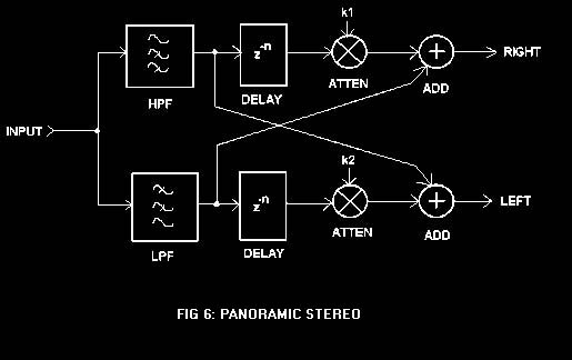
Panoramic Stereo
Another innovation in the Orion is its
Panoramic Stereo feature. This feature employs
high- and low-pass filters combined with
strategically chosen delays to create the
illusion of a three-dimensional listening space.
See Fig 6. With headphones on, low frequencies
appear to come from your left and high
frequencies from your right. Frequencies near the
selected CW offset appear to come from the center.
During a CW pileup, you might be surprised how
that makes signals easier to separate. In
conjunction with Orion's state-of-the-art
filtering system, it also makes them easier to
center in your passband while tuning. Download
the compressed .WAV files here and listen for yourself.
Additional Bonuses for CW Operators
Ten-Tec rigs have been legendary for their
QSK; but this time, we have pulled out all the
stops. Imagine silky smooth full break-in at 60
wpm! Well, the Orion does it.
In addition, you can set your CW rise and fall
times to suit your taste, within limits. With a
fast setting, you can get a harder sound for high-speed
contesting; for rag-chewing, adjust the CW
dynamics slower for a softer sound. The Orion's
internal keyer has adjustable speed and
weighting, of course. Use the CW spotting tone to
zero-beat signals and the built-in keyer memories
to send frequently used messages such as CQs.
FLASH Update
In the best tradition of software radios,
Orion includes FLASH update capability. Your rig
can benefit from software updates as they are
made and new features as they are added. Ten-Tec
continues as the leader with this technology--
Doug Smith, KF6DX.
|
|
|
 Douglas
T. Smith Editorial Services
Douglas
T. Smith Editorial Services